Rotary actuators Series ARP
- Camozzi
- Movement
- Rotary Cylinders
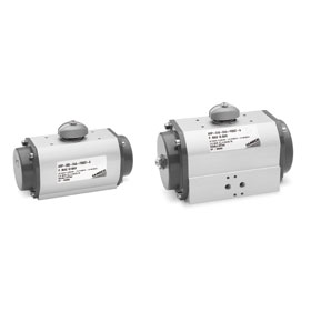
- Rotary actuators Series ARP
 Download PDF (1.370,5 Kb
Model: "Rack & Pinion" - Rotational angles: 90° Sizes: 001, 003, 005, 010, 012, 020, 035, 055, 070, 100, 150, 250, 400
Series general data
| Type of construction |
Rack and pinion type |
| Operation |
spring return (single-acting), double-acting |
| Materials |
extruded AL-profile body (pressure diecasted anodized AL body for mod. ARP400) pressure diecasted AL end caps and pistons / racks (end caps in technopolymer for mod. ARP001) zinc-plated steel pinion POM guide parts NBR seals |
| Sizes |
001, 003, 005, 010, 012, 020, 035, 055, 070, 100, 150, 250, 400 |
| Operating temperature |
- 30°C ÷ 100°C |
| Rotation angle |
90° |
| Type of mounting |
direct to the flange of the valve through screws and bolts, or through mounting kits consisting of bracket and adaptor pin* |
| Operating pressure |
2 ÷ 10 bar |
| Fluid |
filtered air without lubrication. If lubricated air is used, it is recommended to use oil ISOVG32. Once applied the lubrication should never be interrupted. |
| Available spare part kits |
- kits which include sliding parts and seals; - kits containing springs for transforming an actuator from double-acting to single-acting with spring return. |
Code
| ARP |
- |
001 |
- |
1A |
A |
- |
F0300 |
- |
A |
EX |
ARP
|
SERIES
|
001
|
SIZE:
001 = torque force 9 Nm
003 = torque force 24 Nm
005 = torque force 50 Nm
010 = torque force 100 Nm
012 = torque force 120 Nm
020 = torque force 200 Nm
035 = torque force 370 Nm
055 = torque force 597 Nm
070 = torque force 825 Nm
100 = torque force 1122 Nm
150 = torque force 1655 Nm
250 = torque force 2648 Nm
400 = torque force 4800 Nm
|
1A
|
OPERATION:
1A = single-acting, minimum pressure of 4 bar
1B = single-acting, minimum pressure of 5 bar
1C = single-acting, minimum pressure of 5,5 bar
1D = single-acting, minimum pressure of 6 bar
2A = double-acting
|
A
|
ROTATION ANGLE:
A = 90°
|
F0300
|
INTERFACE FOR FLANGE (ISO 5211):
F0300 = flange holes F03
F0305 = flange holes F03 + flange holes F05
F0400 = flange holes F04
F0507= flange holes F05 + flange holes F07
F0700 = flange holes F07
F0710 = flange holes F07 + flange holes F10
F1200 = flange holes F12
F1400 = flange holes F14
F1600 = flange holes F16
F1625 = flange holes F16 + flange holes F25
|
A
|
MATERIALS:
A = standard anodized
E = epoxy (epoxy coating and stainless steel shaft)
C = CNI Kanigen type nickel-plating
W = high temperatures (200°C)
HW = very high temperatures (250°C)
|
EX
|
ATEX certified product
|