

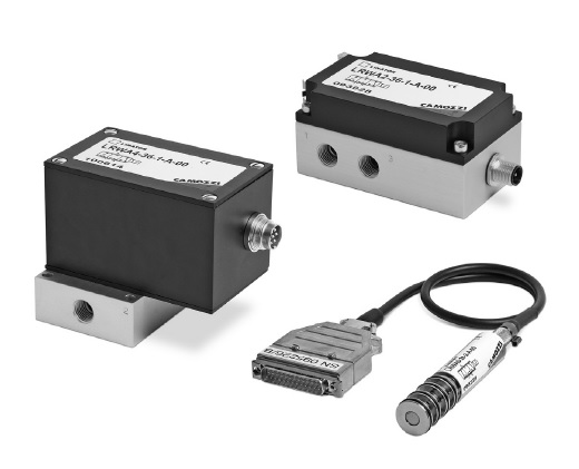
3/3-way directly operated servo valves for the flow control
GENERAL DATA
| Power supply | 24V DC +/- 10%, stabilized, max. 0,8 A |
| Control signal | +/- 10V 100 kohm; 0-10V 100 kohm; 0-20 mA 500 ohm; +/-5 V DC 100 ohm (LRWA4 only) |
| Hysteresis | 1% FS |
| Linearity | 1% FS |
| Switching time | from 0 to 100%: approx. 5 ms; +/- 100%: approx. 7 ms |
| Working temperature | from 0 to 50°C |
| Relative humidity of air | max. 90% |
| Weight of the cartridge | 0.140 kg without cable; (LRWA0); 0.700 kg (LRWA2); 1 kg (LRWA4) |
| Maximum flow rate at 6 bar ΔP 1 bar | 350 Nl/min (LRWA4-34); 450 Nl/min (LRWA0-34, LRWA2-34); 550 Nl/min (LRWA4-36); 690 Nl/min (LRWA0-36, LRWA2-36) |
| Medium | filtered compressed air, unlubricated, according to ISO 8573-1 class 3.4.3, inert gas |
| Supply pressure | -0,9 to 10 bar |
| Leakage | < 1% of maximum flow rate |
| Electrical connecton | SUB-D connector 25 poles with pre-wired cable of 0.5-1-2 m (LRWA0); male connector M12 5 poles (LRWA2); male connector M16 7 poles (LRWA4) |
| L | SERIES: L = proportional servo valves |
| R | TECHNOLOGY: R = rotating spool |
| W | VERSION: w = flow control |
| A | ELECTRONICS: A = analogic |
| 0 | MODEL: 0 = cartridge with fixation slot 2 = compact DIN-RAIL 4 = with sub-base |
| 3 | FUNCTION: 3 = 3-way |
| 4 | NOMINAL DIAMETER: 4 = 4 mm 6 = 6 mm |
| 1 | INPUT COMMAND SIGNAL (Setpoint): 1 = +/- 10 V 2 = 0-10 V 3 = 0-20 mA 4 = +/- 5 V |
| A | FEEDBACK SIGNAL: A = internal encoder |
| 05 | CABLE: 00 = no cable (LRWA2 and LRWA4) 05 = 0.5 m (LRWA0 only) 10 = 1 m (LRWA0 only) 20 = 2 m (LRWA0 only) |